The strength of a culvert depends on the strength of the materials that are used and the shape of the culvert barrel. Determine the allowable headwater elevation Section 3-32 3.

Concrete Box Culvert House Google Search Culvert Shipping Container House Engineering
Pipe Culverts Page 25 Design Example A.

. General Culvert Design Method 1. Section VI contains an example procedure for design of a riprap outlet commonly. 13 with hydrologic storage routing and special culvert design information.
The emphasis in this Chapter is on the design of culverts for urban stormwater drainage. 1 b ft h ft ss H V d ft W ft W ft 8 6 1 1 4 6 and 12b 2 n 1 2 to accommodate an operating road. Or m SI Q discharge cfs US.
This technical note also provides guidelines for the design of the connection between the culvert and precast headwall unit using cast in-situ headwall extensions behind the precast headwall or bolted connection and cast in- situ or precast cutoff wall in front of the apron. DATA Discharge through pipe culvert. Section IV contains an example of a preformed scour hole design commonly used below a culvert pipe or pond barrel pipe outlet.
When there is an adequate height between pipe top-level and road top-level parts of loads applied on the road will transfer through the compacted soil between the pipe from the arching action. Major design parameters for culvert design are the diameter and slope of the pipe for a specified culvert material. 42 Structural Design of Culverts 421 Introduction Structural design of a culvert must be performed to ensure that the culvert is strong enough to resist the loads that will be imposed upon it.
Generally the hydraulic control in a culvert will be at the culvert outlet if the culvert is operating on a mild slope. These actions need to be considered during the design of pipes and the pipe culvert bridge. See the Bureau of Local Roads and Streets Manual for guidance on Local Agency culverts.
Flexible pipe structures corrugated steel thermoplastic etc. Inlet control usually occurs if the culvert is operating on a steep slope. Hydrologic analysis methods are described and references cited.
The Districts with assistance from the BBS as needed. These charts and nomographs are based on data from hydraulic tests and on theoretical calculations. Calculate the culvert design flows Section 3-31 2.
Culvert Extension - A portion of a culvert built beyond the limits of a previously existing culvert. Culvert Manual CM 34 - LRFD Culvert Design Loads May 2019 Page 5 According to Article 121121 live load distribution is dependent on fill height. And concrete pipe culvert 2 applications.
DESIGN OF PIPE CULVERT. BBS will provide assistance on design of new culverts not meeting Design Table requirements and in need of special design. The design procedures contained in this section are for the design of culverts for a constant discharge considering inlet and outlet control.
Section V contains a design example of an outlet protection used below of a pond barrel pipe. Pipe Culvert Inlet Control Design Spreadsheet Calculations. Proposed roadway stationing of the culvert location.
The correlation between the design equations and the design nomographs is not exact. Virtuosity is Industry-Leading in Design Construction and Infrastructure Software. Circular pipe culverts are widely used in transportation applications to transport stormwater under roadways railways etc.
DIAMETER OF PIPE Discharge 4 x d2 x V d. Loading Example A culvert on a roadway corridor has the parameters given below. 5 combines culvert design information previously contained in Hydraulic Engineering Circulars HEC No.
The following are discussions of important concepts in culvert design. Properties of the canal section are. For example a circular shape.
The result is a comprehensive culvert design publication. The procedures for the hydraulic design of culverts are based on Hydraulic Design of Highway Culverts Hydraulic Engineering Circular No 5 US Federal Highway Administration 1985. Culvert hydrology and hydraulic calculations as described in Section 3-3 and Table 3-2.
The pipe type culvert includes head wall at both end of road RCC hume pipe embedded in concrete. An equation that relates culvert parameters for inlet control conditions in a pipe culvert design spreadsheet is. Determine the type of control that exists at the design flows either inlet control or outlet control Section 3-34 5.
Examples of flexible pipes are plastic and thin walled metal pipes. There is scatter in the test data and the selection of a best fit design equation. The culvert was founded at a location with no ground water problem.
Corrugated metal and concrete are used for many of these pipe culverts. If the culvert discharges to a lake pond or other major water body the expected high water elevation for the culvert design frequency of the particular. Culvert pipe under roadway approaches ie driveway shall have.
Or m 3. The minimum diameter of culvert pipes under a main roa dway shall be 18 inches. 2132 Multi-Barrel Cast-in-Place Concrete Box Culverts.
Hydraulic Design series No. Top level of embankment. Concrete box culverts and rigid pipes are classified as rigid culverts and are assumed to carry the design loads internally with limited requirements or benefit of the soil.
HW headwater depth above inlet invert ft US. Bed level of flow. Impact factor AxV.
Velocity of flow through pipe. 16 Concrete Pipe Design Manual American Concrete Pipe Association 222 W. Adopt RCC NP3 heavy duty non.
Or m SI D inside height of the culvert ft US. Box Culvert - A culvert in the shape of an enclosed rectangle and consisting of a bottom slab two wall elements and a top slab. Las Colinas Blvd Suite 641 Irving Texas 75039-5423 972-506-7216 Fax 972-506-7682 Illustration 31 - Factors Affecting Culvert Discharge D Inside diameter for circular pipe HW Headwater depth at culvert entrance L Length of culvert.
The distribution of live loads for fills 2 feet shall be according to Article 46210 and for fills. Ad Powerful Easy-to-Use Calculator Product for Design Analysis of Culvert Hydraulics. The cross drainage channel is wide shallow and poorly defined both at inlet and outlet.
Designer - Individuals designated by the Structural Engineer to use this manual to design and detail culverts. HDS-5 culvert design methods are based on design charts and nomographs. Determine the tailwater elevation at the design flow Section 3-33 4.
11 This submission contains the design procedure of CROSS DRAINAGE WORK with Pipe culvert type. C h a p t e r 9 ²C u l v e r t s 9-5. Of the downstream culvert may establish the design tailwater depth for the upstream culvert.
The head wall supports the road embakment fill at both end of. Flexible Pipe - a structure that transmits the load on the pipe to the soil at the sides of the pipe. Using any suitable means obtain the design internal forces induced in the members of the culvert due to the anticipated loading conditions when the culvert is empty under the following site conditions.
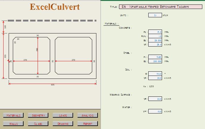
Concrete Box Culvert Analysis And Design Spreadsheet

Wingwall Of Culvert Free Drawing Culvert Bridge Design Autocad
Reinforced Concrete Box Culvert Using Sap2000 This Sap2000 Tutorial Provides Modelling Analysis Design Of Reinforced C Reinforced Concrete Sap2000 Concrete

Cross Section Of Double Hole Box Culvert Design Load Level A Urban Download Scientific Diagram

Design Draw A Pipe Culvert With 3 Vents Examples Part 1 Youtube
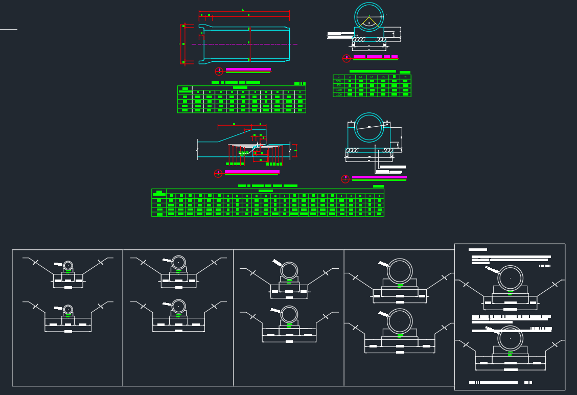
Pipe Culvert Details Autocad Drawing

Design Draw A Pipe Culvert With 3 Vents Examples Part 1 Youtube

Recommendations For Design Of Reinforced Concrete Pipe Journal Of Pipeline Systems Engineering And Practice Vol 1 No 1
0 comments
Post a Comment